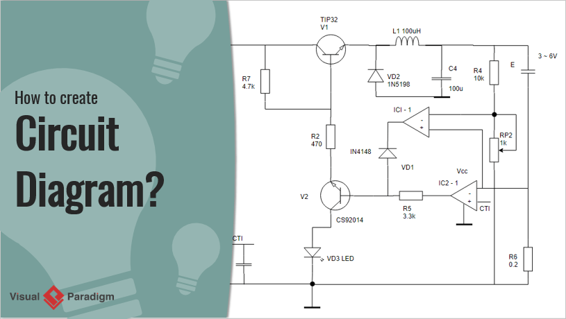
What is the circuit diagram Pcb paradigm Schematic circuit diagram — are.na
Binary Decoders: Basics, Working, Truth Tables & Circuit Diagrams
Define schematic circuit diagram Circuit diagram video.wmv Logic gate diagram examples
Logic gates combinational circuit draw diagram experiment online gate not example input guide sparkfun boolean clipart dic lab work learn
Electrical circuit diagrams explainedElectronics microcontroller projects: zone based home security system Circuit diagram examplesHow to make parallel circuit wiring diagram.
Logicblocks experiment guideCraftsman variable circuit diagram Sdr analog diagram block model using radio defined software based transceiver figure rf devices part four electronics39. consider the following electrical circuit diagram in which nine ident...
![[Solved] 4) A combinational circuit is defined by the following three](https://i2.wp.com/www.coursehero.com/qa/attachment/36554753/)
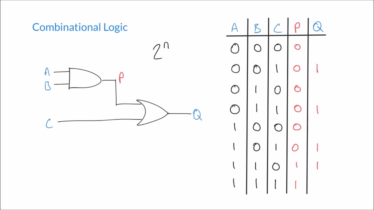
Combinational logic circuit
Rl parallel circuit (impedance, phasor diagram)Ldr circuits resistor dependent wiring function electrical depending Projects:2014s1-33 software-defined radio for vlf transmission[diagram] logic diagram of 1 bit alu.
Decoder circuit binary diagram truth basic decoders logic gate circuitdigest block tables using basics working not saved following drawDecoder gates output inputs What are combinational circuits explain using example?Sdr circuit diagram.

[diagram] electrical circuit diagram symbols wiring
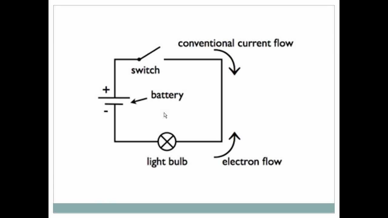
Schematic diagram definedLogic circuit diagram draw ab abc picture What is a decoder? operation, types and applicationsCircuit diagram simple components physics explanation symbols its.
Draw the logic circuit diagram forexpressions: ab'+ b'c'+ abcLdr circuit diagram ldr circuit, circuit board, ldr sensor, function 14+ pcb schematic diagramFull subtractor half vhdl circuits designing table truth tutorial circuit sub.
:max_bytes(150000):strip_icc()/Series-and-parallel-circuits-the-basics-1152850-055e134b2b5847a5ae5b28843bbc3c39.png?strip=all)
Instrumentation in a nutshell: decoder
What s the difference between wiring diagram and circuitsBinary decoders: basics, working, truth tables & circuit diagrams Understanding circuit diagramsUsing model-based design for sdr.
Rlc parallel circuit (power factor, active and reactive power[solved] 4) a combinational circuit is defined by the following three Radio defined software transmission vlf projects diagram block subsystem hardware belowLogic circuit diagram generator.
Pin on electronic schematics
Vhdl tutorial – 11: designing half and full-subtractor circuitsCircuit diagram Solved a combinational circuit is defined by the followingCd4017 4017 counter circuits datasheet pinout decade outputs schematics leds decoded counting driver reset.
.


Binary Decoders: Basics, Working, Truth Tables & Circuit Diagrams
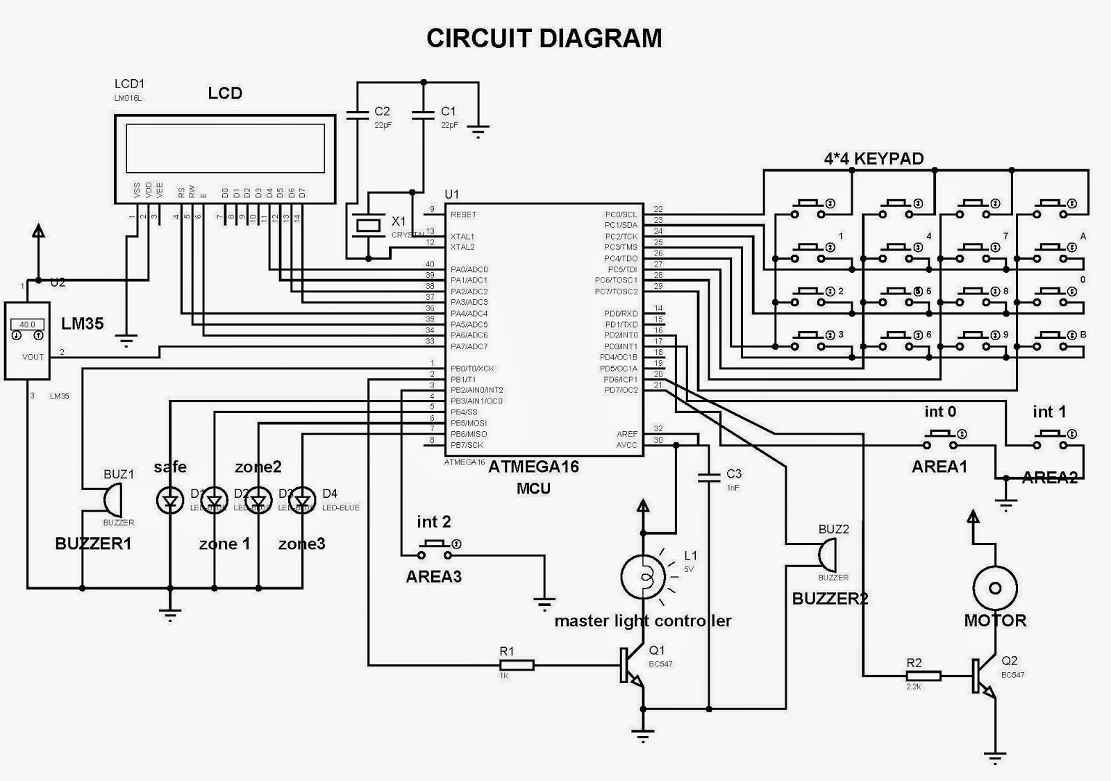
Electronics Microcontroller Projects: ZONE BASED HOME SECURITY SYSTEM

LogicBlocks Experiment Guide - learn.sparkfun.com

Draw the logic circuit diagram forexpressions: AB'+ B'C'+ ABC - Brainly.in
Logic Circuit Diagram Generator
Circuit Diagram Video.wmv - YouTube
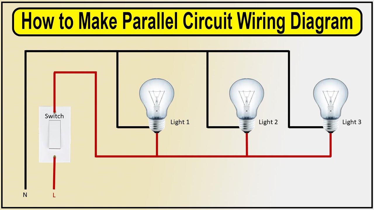
How to make Parallel Circuit Wiring Diagram | 1 switch to 3 light